Unfortunately, getting laid off at HP caused me to stop thinking in terms of carbon fiber composite tubes to make a half-Suerrier truss, and working for the State of Idaho does not incline me towards such a high technology, but expensive solution. But maybe I do not need to. I was trying to figure out how to calculate the deflection of a truss, but other things came up, and I was not able to pursue finding this information.
I did find a program called TDT4WIN (Telescope Design for Windows) here which calculates a variety of useful information for designing telescopes, including Suerrier truss sag. It purports to approximate what a finite element analysis program does. It calculates the sag for one truss at a time. If you have an eight tube Suerrier truss (for trusses), and the telescope is parallel to the ground, with two of the trusses vertical and two horizontal, then two of the trusses carry almost all the weight (although the two horizontal trusses do provide some benefit). If you rotate the tube 90 degrees, the two trusses that were horizontal are now vertical, and are doing the support. If you rotate the tube 45 degrees, the support is now shared equally by all four trusses. For this reason, TDT4WIN says to compute the sag for one of the trusses with half the weight the truss will be supporting; both sides should have similar sag.
A similar analysis tells me that a six tube Suerrier truss (three trusses) has similar characteristics as you rotate it. Again, do the calculation for one truss; the other side of the telescope will be supported by the other two trusses. Because of the 60 degree rotation relative to gravity, the net effect of those other two trusses will roughly match the one that is vertical.
Using the Young's Modulus for aluminum (about 10 million pounds per square inch), and a cross section area for the readily available 1", .050" wall aluminum tubes, and supporting six pounds (half the weight of the upper telescope assembly plus half the weight of the tubes), for a length of 60" and a 19" separation at the base of the truss, it calculates a sag of 0.001889 inches--which is well within the realm of acceptable. (Remember that this is the maximum sag, when the telescope is horizontal, a fairly rare situation for an astronomical telescope.) Most of the time, the sag will be less because the telescope will be pointing closer to vertical. To those of you with experience with these things--does this seem like a plausible number?
I plugged in the numbers for carbon fiber composite tubing as well: 20 million psi for the Young's modulus (although some advertise 33 million psi), for a 1" .060" wall tube, and while it was stiffer, it was vastly more expensive. (Like more than $600 for the tube.)
The big goal is to reduce the weight. The six aluminum tubes are 5.24 pounds; six carbon fiber composite tubes are 2.08 pounds. This is a three pound difference for what appears to be a thousandths of an inch difference in sag.
Square tube is probably a waste, Remember that the rigidity of a rectangular section is much higher along its long dimension than the thin one. You could use twice as many L- or T-sections as square tubes, and also benefit from not bolting through empty space when it comes to attaching them. However, for real rigidity, you can't beat triangles, and for that I suggest that you not depend just on the rigidity of the struts, but form a larger scale truss by connecting the rods together with angled pieces.
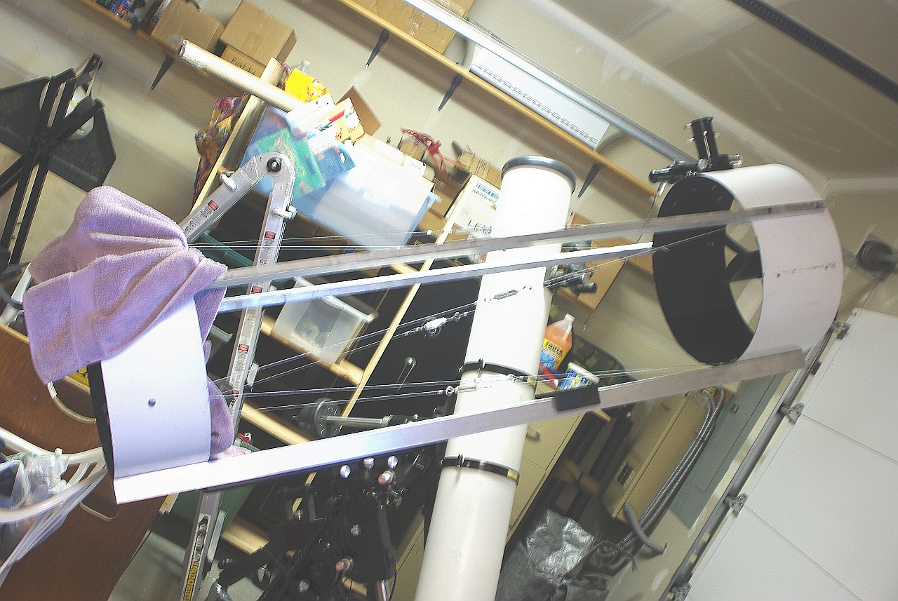
ReplyDeleteTaking a closer look, I can kind of see what you're doing with the tensioned wires, but I think that's not such a good idea for a structure subject to loads from so many different directions as it moves. Effectively, you're making it out of springs, so no wonder it flexes when you reorient it.
It is precisely the issues you mention that are the reason for a Suerrier truss, using round tubes to form triangles. The tensioning wires were definitely an improvement over what I had, but they still leave room for improvement.
ReplyDeletehow you connect the elements together will have a huge effect on the rigidity of the truss. if the connections have any give in them, the truss will not be as rigid as the software thinks it will be. the software is assuming the connections are as rigid as the base metal. welding is the only way to achieve that.
ReplyDeleteNo question. The connectors are at http://www.focuser.com/cgi-bin/dman.cgi?page=category&plugin=dstore.cgi&category=6 .
ReplyDelete